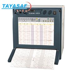
Everest X-HS采集器工作站
| 订货号: | MM-02108-00 |
| 产地: | 美国 |
| 品牌: | |
| 开发编号: | N |
| 市场价: | ¥ |
| *此产品根据配置不同价格不同 |
| *此价格为参考价格,具体价格以订单合同为准 |
- 我在现场:
- 产品视频:

- 产品描述
- 技术参数
- 技术文档
- 相关产品
- 明细价格
- 购买流程
产品描述:
-Large 18.1" color display for real-time data viewing
-Intuitive touch-screen interface simplifies setup and operation
-Up to 32 analog or digital inputs
-Virtual ChartT efficiently stores data while saving paper
-Ethernet interface for command and control
-High-resolution chart printing for clear, crisp traces
The Everest X is a powerful recording platform designed for the unique demands of aerospace testing. Combining a high resolution 18" display, touch panel interface and superb quality chart output, the Everest X is ideal for applications such as flight testing , missile testing , flight simulation and satellite telemetry. With the Everest X system, you can view and print your data in real-time as well as mark specific portions of the data for later review. A customizable touch-panel interface makes the Everest X into a dedicated recorder for your specific requirements.
High Resolution Display
The Everest X has a high resolution, 18" color display for viewing waveforms in real-time. Clearly visible from any angle, the display can be customized with different colors for waveforms, grids, timing marks and text. Signals can even change colors when they exceed preset levels.
The Everest X has a high resolution, 18" color display for viewing waveforms in real-time. Clearly visible from any angle, the display can be customized with different colors for waveforms, grids, timing marks and text. Signals can even change colors when they exceed preset levels.
Easy-to-use Touch-Panel Controls
The touch-panel control makes your user-interface easily customizable. The touch-panel also allows you to instantly mark a point of interest and add a notation for later review.
The touch-panel control makes your user-interface easily customizable. The touch-panel also allows you to instantly mark a point of interest and add a notation for later review.
High Resolution Chart Output
The high print quality of the Everest X produces the clearest and most accurate charts available. Chart formats are completely flexible.
The high print quality of the Everest X produces the clearest and most accurate charts available. Chart formats are completely flexible.
Store all your data with Virtual Chart
Virtual Chart allows you to save large amounts of data to an on-board hard drive. Virtual chart data can be reviewed on the display, played back to the chart or even taken to a PC for offline analysis.
Virtual Chart allows you to save large amounts of data to an on-board hard drive. Virtual chart data can be reviewed on the display, played back to the chart or even taken to a PC for offline analysis.
Analog or Digital Inputs
Everest X can accept up to 32 analog inputs. Digital data can also be input via Ethernet or other optional interfaces. The Everest X accepts IRIG A, B, H and NASA 36.
Everest X can accept up to 32 analog inputs. Digital data can also be input via Ethernet or other optional interfaces. The Everest X accepts IRIG A, B, H and NASA 36.
Real-time with Look Back
A real-time look back feature allows viewing of historical data. A split screen display allows this data to be viewed without interrupting real-time recording.
A real-time look back feature allows viewing of historical data. A split screen display allows this data to be viewed without interrupting real-time recording.
技术参数:

泰亚赛福作为众多知名品牌的合作伙伴,优惠的价格+完善的售后服务体系向您提供产品。font>
Specifications
|
Color Display | |
|
Type |
Active matrix color LCD (TFT) |
|
Viewing Area |
18.1-inch (diagonal) |
|
Resolution |
1280 x 1024 |
|
Touch Screen Type |
Resistive (resolution <1mm) |
|
Functions |
User interface with touch based icons and menus; Waveform monitoring to full speed; Review previous waveform histories while recording; Overlay numeric values in Engineering Units; pen style indicators for point of real-time; Overlay user comments with touch panel |
|
Chart Recorder | |
|
Recording Method |
Direct Thermal |
|
Chart Width |
414 mm (16.3 in) |
|
Resolution |
12 dpm (300 dpi) |
|
Print Speed |
1 mm/min to 100 mm/sec at 12 dpm; 101 mm/sec to 200 mm/sec at 6 dpm |
|
Speed Accuracy |
± 2% |
|
Dual Speed |
Automatic speed change with trigger or time |
|
Remote Start/Stop |
TTL level, switch closure or computer interface |
|
External Speed |
Speed synchronized to TTL source |
|
Maximum Waveform Size |
170 mm |
|
Amplitude Grids |
32 independent up to 170 mm wide. Auto or manual grid design and placement |
|
Time Marking |
Tri-state (x1, x10, x100) mark on either chart edge. Selectable mark (0.02 to 1 second or external) with Grid Synchronization |
|
Annotation |
System Log printed automatically (time, date, speed); Each grid associated with a line of text (128 ASCII characters); An On-demand text buffer is available (128 characters) |
|
Signal Conditioner |
Auto annotation using grid buffers; Top and bottom grid values labeled |
|
Channel ID |
Each channel labeled with channel number |
|
Trace Thickness |
User adjustable |
|
Paper |
Z-fold pack (400 sheets) or roll available; Each is 397 ft |
|
Remote Start/Stop |
TTL level, switch closure, or computer interface |
|
Computer Interface | |
|
Host Control |
10/100 Base T Ethernet, RS-232, GPIB (optional) |
|
Digital Data |
10/100 Base T Ethernet |
|
Power Specifications | |
|
Input Voltage Range |
100 to 250 VAC |
|
Frequency Range |
47 to 63 Hz |
|
Input Power Consumption |
300 Watts (typical) - 500 Watts (maximum) |
|
Leakage Current |
0.75mA maximum |
|
Safety |
UL3101-1 |
|
Emissions |
FCC Part 15 Class A, EN55011 |
|
Power Harmonics |
IEC 1000-3-2 |
|
Physical Specifications | |
|
Mounting |
Benchtop or 19" rack |
|
Dimensions |
21"H x 19"W x 14.5"D (Rack) |
|
Weight |
62 lbs. |
|
Operating Humidity |
10% to 95% non-condensing |
|
Operating Temperature |
5 to 40°C (40 to 105°F) |
|
Alarm Specifications | |
|
Indications |
Waveform color change on display |
|
Test Types |
Window; All active signals monitored simultaneously |
|
Output |
2 TTL outputs, user Definable |
|
Trigger Specifications | |
|
Window |
High and low thresholds, inside and outside |
|
Slope/Level |
Rising, Falling or either |
|
Slew |
Time periods from 0.01 to 10 seconds |
|
Event |
Binary combination of active events |
|
Other Sources |
Manual and external inputs |
|
Worst Case Latency |
1 millisecond |
|
Output |
TTL, net of trigger conditions |
|
Waveform Channels | |
|
Modules |
Maximum of four modules (DM1 Series or SM2 Series) can be installed for up to 32 waveform channels |
|
Utility Port | |
|
Functions |
Trigger In, Alarm Out A or B, Remote Arm, Security, Remote Abort, Chart Mark, Trigger Out, External Motor Clock, External Run/Halt, Programmable Input (can be set to cause on-demand buffer, channel ID or channel labeling), and TTL 5V |
|
Connector |
15-pin "D" shell |
|
Other Connectors | |
|
Printer Port |
PC Parallel Port (25-pin "D" shell) |
|
Mouse, Keyboard |
PS/2 |
|
Video |
15-pin "D" shell |
|
Waveform History Specifications | |
|
Method |
Saves full bandwidth line segments |
|
Media |
SRAM with archive to disk |
|
Time Base Resolution |
Better than 1 millisecond at 100 mm/sec |
|
Record Size |
10,000 line segments (over 800 mm of chart) |
|
Circular Buffer |
Saves time period leading up to and including stimulus |
|
Stimulus |
Touch Panel or trigger |
|
Content |
Waveforms, events, grid and time marks, alarms and highlights |
|
Review |
Split screen while recording |
|
Archive |
Save to hard drive or to removable media |
|
External Time Code | |
|
Formats |
IRIG A, IRIG B, IRIG H, NASA 36; Amplitude Modulated or TTL |
|
Amplitude Modulated Input Voltage Limits |
0.5Vp-p to 10Vp-p |
|
Maximum Safe Input |
+10V or -10V |
|
Time Base Variations |
x1/2, x1, x2 |
|
IRIG On Time Mark Accuracy |
±1msec or 1 chart segment (whichever is greatest); 1/12 mm on the chart |
|
Multicard Reader | |
|
Format |
PC Format |
|
Media |
USB 2.0, CompactFlash (CF), Memory Stick (MS), Secure Digital (SD), Micro Secure Digital (Micro SD), Multi Media Card (MMC), SmartMedia (SM), XD-Picture Card (XD) |
|
Functions |
Setup files, software upgrades, and data transfer/archive |
|
Realtime Recording Formats | |
|
User Defined Formats |
The user can design unique charts using standard menus. These formats can be saved to the hard drive or to removable media |
|
Data Logger |
Numeric reporting of waveform data in engineering units |
|
Dual Speed |
System toggles between any two chart speeds based on time inteval or trigger |
|
Constant Chart Speed |
Constatn chart output regardless of display speed choice |
|
Highlight (chart delay) |
Delays printing of the chart by one screen in order for user comments to be entered on the touchscreen. |
|
Annotation | |
|
System Log Channel |
Prints time, date, speed, time base and function on the left chart edge |
|
Waveform ID |
An identification code printed next to each waveform |
|
Waveform Buffers |
32 annotation buffers. Standard buffers are128 characters long |
|
On-the-fly buffer |
One additional 128 character annotation buffer, which can be positioned anywhere across the chart and printed with a keystroke |
|
Signal Conditioner Buffer |
Internal gain and zero position settings are automatically printed as the last 40 characters of the waveform text buffers |
|
Highlight Comments |
User definable, touch screen activated comments are printed on the chart while in highlight mode |
|
Standard Event Markers | |
|
System Event (Chart Mark) |
Standard with glitch capture. Operates from front panel key or external input (TTL or switch closure) |
|
Tri-level Time |
x1, x10, x100 based on user choice of reference |
|
Tri-level Reference |
Internal: 0.01, 0.02, 0.04, 0.1, 0.2, 0.4, 1.0, 3.6, 6 sec; External: any available time code start pulse |
|
Tri-level Location |
Either right edge, left edge or both, selectable |
|
Additional Markers |
8 per SM2 Series Module |
|
Platforms Available | |
|
Everest-HSR |
High Security, Rackmount. Base platform Everest with all non-volatile media being removable |
|
Everest-HS |
High Security Everest in bench-top case |
|
Virtual Chart (optional) |
|
|
Recording Method |
Internal 73 Gbyte hard drive |
|
Data Presentation |
Play data back to Everest display and/or chart; Archive to PC for review |
|
Signal Module Specifications (SM2) | |
|
Waveform Inputs |
8 on module |
|
Waveform Type |
Single-ended voltage |
|
Input Coupling |
DC |
|
Connector |
BNC |
|
Max. Rated Input |
±50V |
|
Specified Measurement Ranges |
4 to40Vfs; 0.5 to 5Vfs |
|
Available Ranges |
1 to 40 Vfs; 0.1 to 5 Vfs |
|
Voltage Accuracy |
±0.5% of the attenuator |
|
Net Bandwidth |
15 kHz (-3dB) |
|
Minimum Input Impedance |
>150 kOhms |
|
Intrinsic Noise |
0.5% of the attenuator |
|
Baseline Drift with Temperature |
0.05% of the attenuator per °C |
|
Filter Choices |
Low pass with stops from 10 to 10,000 Hz; High pass with starts from 0.1 to 100 Hz; Notch with 50 or 60 Hz Center |
|
RMS Time Constant |
Selectable from 0.02 to 2 seconds |
|
Automatic Calibration |
To internal or external signal source (DAC cal) |
|
User Engineering Units |
Yes, with automatic scaling |
|
Waveform Testing |
All active waveform channels monitored simulataneously |
|
Event Inputs |
8 per module |
|
Event Types |
TTL with pull ups (0 to 5V) |
|
Event Response |
20 Microseconds minimum duration |
|
Data Capture (optional) |
Up to 400,000 samples per channel; 120 kSamples per second per channel; includes glitch capture to ensure bandwidth |
|
Signal Module Specifications (SM2D) | |
|
Waveform Inputs |
8 on module |
|
Waveform Type |
Differential voltage |
|
Input Coupling |
DC |
|
Connector |
D-shell (25 pin) |
|
Max. Rated Input |
±50V |
|
Specified Measurement Ranges |
4 to40Vfs; 0.5 to 5Vfs |
|
Available Ranges |
1 to 40 Vfs; 0.1 to 5 Vfs |
|
Voltage Accuracy |
±0.5% of the attenuator |
|
Net Bandwidth |
15 kHz (-3dB) |
|
Minimum Input Impedance |
>150 kOhms |
|
Intrinsic Noise |
0.5% of the attenuator |
|
Baseline Drift with Temperature |
0.05% of the attenuator per °C |
|
Filter Choices |
Low pass with stops from 10 to 10,000 Hz; High pass with starts from 0.1 to 100 Hz; Notch with 50 or 60 Hz Center |
|
RMS Time Constant |
Selectable from 0.02 to 2 seconds |
|
Automatic Calibration |
To internal or external signal source (DAC cal) |
|
User Engineering Units |
Yes, with automatic scaling |
|
Waveform Testing |
All active waveform channels monitored simulataneously |
|
Event Inputs |
8 per module |
|
Event Types |
TTL with pull ups (0 to 5V) |
|
Event Response |
20 Microseconds minimum duration |
|
Data Capture (optional) |
Up to 400,000 samples per channel; 120 kSamples per second per channel; includes glitch capture to ensure bandwidth |
|
Signal Module Specification (DM1) | |
|
Number of Signals |
8 waveform and 8 event per module |
|
Input Type |
Parallel, long line (RS-485 differential) |
|
Connector |
50-pin Centronix style |
|
Interface Bandwidth |
500 kHz |
|
Maximum Channel Rate |
50,000 samples/second |
|
Filter Choices |
Low Pass with stops from 1 Hz to 10000 Hz; High Pass with starts from 0.1 Hz to 100 Hz; Notch with 50 or 60 Hz center |
|
RMS Time Constant |
Selectable from 0.02 to 2 seconds |
|
User Engineering Units |
Yes |
|
Data Capture Option |
Up to 400,000 samples per channel and 120 kSamples/second/channel |

泰亚赛福作为众多知名品牌的合作伙伴,优惠的价格+完善的售后服务体系向您提供产品。font>
技术文档:

泰亚赛福作为众多知名品牌的合作伙伴,优惠的价格+完善的售后服务体系向您提供产品。font>
- 在线浏览:
- 文档下载:

泰亚赛福作为众多知名品牌的合作伙伴,优惠的价格+完善的售后服务体系向您提供产品。font>
相关产品:

泰亚赛福作为众多知名品牌的合作伙伴,优惠的价格+完善的售后服务体系向您提供产品。font>
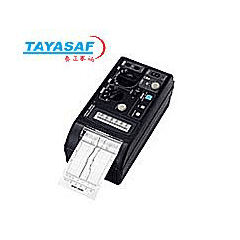 8206-10记录仪订货号:MM-00489-00
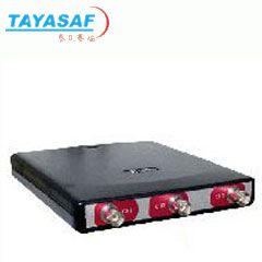 HS3基于PC的数据记录仪订货号:MM-01054-00
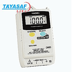 3637-20电压记录仪订货号:MM-01731-00
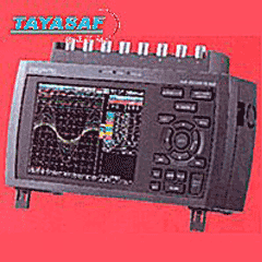 GL900记录仪订货号:MM-01811-00
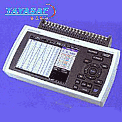 GL800记录器订货号:MM-01791-00
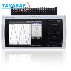 GL800记录仪订货号:MM-02604-00
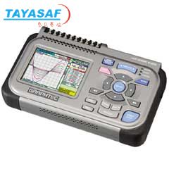 GL200记录仪订货号:MM-02608-00
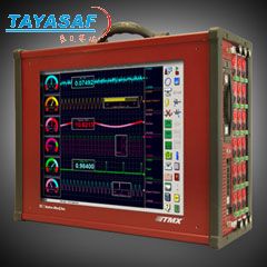 高速数据采集系统订货号:MM-01895-00
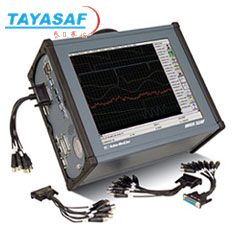 Dash® 32HF-HS多通道高频记录仪订货号:MM-01923-00
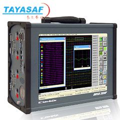 Dash® 20HF-HS多通道高频记录仪订货号:MM-01926-00
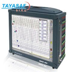 Dash® 18X便携式数据记录仪订货号:MM-01931-00
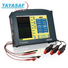 Dash® 8XPM数据采集器订货号:MM-02093-00

泰亚赛福作为众多知名品牌的合作伙伴,优惠的价格+完善的售后服务体系向您提供产品。font>
明细价格:

泰亚赛福作为众多知名品牌的合作伙伴,优惠的价格+完善的售后服务体系向您提供产品。font>
| 定货号 | 产品名称 | 规格配置 / 简介 | 市场价/(会员价) |
|---|---|---|---|
| MM-02108-00 | Everest X-HS采集器工作站 | /() |

泰亚赛福作为众多知名品牌的合作伙伴,优惠的价格+完善的售后服务体系向您提供产品。font>
购买流程:

泰亚赛福作为众多知名品牌的合作伙伴,优惠的价格+完善的售后服务体系向您提供产品。font>
①购买产品:点击“生成订单”→填写产品数量、联系方式并提交→会员顾问订单处理→合同签订。
②咨询产品:请联系会员顾问或致电会员客服电话。
③如果您还不是我们的会员,请先注册。
④最小起订数量:1
注意:本产品唯一个人现金委托收款人,如汇入其它个人账户本公司不承担任何责任
维护担当:
上线时间:
投诉电话:13801126385 13911302309
②咨询产品:请联系会员顾问或致电会员客服电话。
③如果您还不是我们的会员,请先注册。
④最小起订数量:1
注意:本产品唯一个人现金委托收款人,如汇入其它个人账户本公司不承担任何责任
维护担当:
上线时间:
投诉电话:13801126385 13911302309
联系方式
电话北京:400-000-1836 分机 或拨0转总机
上海:021-54248686 分机225 或拨0转总机
上海:021-54248686 分机225 或拨0转总机
传真北京:010-84852750/84854139
上海:021-64418200
上海:021-64418200

泰亚赛福作为众多知名品牌的合作伙伴,优惠的价格+完善的售后服务体系向您提供产品。font>
您最近浏览的商品


 美国Astro-Med,Inc