
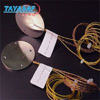
HT-50热流传感器
| 订货号: | MM-37513-00 |
| 产地: | 美国 |
| 品牌: | |
| 开发编号: | N |
| 市场价: | ¥ |
| *此产品根据配置不同价格不同 |
| *此价格为参考价格,具体价格以订单合同为准 |
- 我在现场:
- 产品视频:

- 产品描述
- 技术参数
- 技术文档
- 相关产品
- 明细价格
- 购买流程
产品描述:
FOR PRECISE MEASUREMENT OF
HEAT FLUXES
Heat Fluxes To 10 Btu/hr ft
Temperature Range to 18000F.
Rapid Response (0.1 Secs.)
Linear Output
Accuracy 5%
Negligible Thermal Resistance
No Power Supply Required
PRINCIPLE
The flow of heat to, or from a surface on which the transducer is placed creates a small temperature difference between the upper and lower surfaces of the transducer. These surfaces are in thermal contact with a miniature, high temperature thermopile which generates
a direct current signal from this temperature difference. The thermoelectric element yields signals which may be measured by a microvolt meter. Because each unit is self-powered, no excitation voltage is necessary. The thermal resistance introduced by the transducer is negligible for all practical purposes.
CALIBRATION
ITI Thermal Flux Meters are individually calibrated at a base temperature of 70 F. An absolute calibration technique is used to determine the meter constant to the required accuracy, and verified by calculation. A temperature correction curve for elevated temperatures is also provided.
SPECIFICATIONS
Temperature Range . .........................- 425 F. to 1800 F.
(2000 F. in Vacuum)
Maximum Flux Density..............................10 Btu/hr ft
Material................................................Stainless Steels
Time Constant.................................................0.1 Secs.
Size . . ............................................0.100”x 5/8”x 5/8”
Sensitivity......................................150 Btu/hr ft �Volt
Accuracy....................................................................5%
APPLICATION
The Model HT-50 Thermal Flux Meter is a solid state, flat-plate, metallic transducer designed to measure heat flow directly. This transducer is placed upon any surface through which the heat flow is to be measured.
The unit will measure heat flow to, or from any surface. In many cases, the transducers may also be installed internally within any barrier with no loss of accuracy.
Application areas include:
Furnace/Boiler Heat Flow
High Temperature Heat Transfer
Engine Heat Loss Measurements
Physical Property Determinations
Aeronautical and Space Technology
OPERATION
The transducer may be attached to the heat transfer surface by either clamp, or ceramic cement. The D.C. signal generated by the transducer from the heat flow is conducted to the readout by means of a cable. When the transducer attains equilibrium (app. 0.1 sec.) with
the surface, the generated voltage will be proportional to the heat flux. When this output voltage is multiplied by a specific calibration constant, which is supplied with each transducer, the resulting value will be heat loss/gain in terms of Btu/hr ft.
技术参数:

泰亚赛福作为众多知名品牌的合作伙伴,优惠的价格+完善的售后服务体系向您提供产品。font>

泰亚赛福作为众多知名品牌的合作伙伴,优惠的价格+完善的售后服务体系向您提供产品。font>
技术文档:

泰亚赛福作为众多知名品牌的合作伙伴,优惠的价格+完善的售后服务体系向您提供产品。font>
- 在线浏览:
- 文档下载:

泰亚赛福作为众多知名品牌的合作伙伴,优惠的价格+完善的售后服务体系向您提供产品。font>
相关产品:

泰亚赛福作为众多知名品牌的合作伙伴,优惠的价格+完善的售后服务体系向您提供产品。font>
 HFM201热流计订货号:MM-15443-00
 HFM-215多点热流计订货号:MM-37464-00
 SIP-030热流计订货号:MM-37465-00
 SIP-050热流计订货号:MM-37466-00
 SIP-075热流计订货号:MM-37467-00
 SIP-100热流计订货号:MM-37468-00
 SIP-125热流计订货号:MM-37469-00
 SIP-150热流计订货号:MM-37470-00
 SIP-250热流量计订货号:MM-37471-00
 SIP-300热流量计订货号:MM-37472-00
 SIP-400热流量计订货号:MM-37473-00
 SIP-05-12热流量计订货号:MM-37474-00

泰亚赛福作为众多知名品牌的合作伙伴,优惠的价格+完善的售后服务体系向您提供产品。font>
明细价格:

泰亚赛福作为众多知名品牌的合作伙伴,优惠的价格+完善的售后服务体系向您提供产品。font>
| 定货号 | 产品名称 | 规格配置 / 简介 | 市场价/(会员价) |
|---|---|---|---|
| MM-37513-00 | HT-50热流传感器 | /() |

泰亚赛福作为众多知名品牌的合作伙伴,优惠的价格+完善的售后服务体系向您提供产品。font>
购买流程:

泰亚赛福作为众多知名品牌的合作伙伴,优惠的价格+完善的售后服务体系向您提供产品。font>
①购买产品:点击“生成订单”→填写产品数量、联系方式并提交→会员顾问订单处理→合同签订。
②咨询产品:请联系会员顾问或致电会员客服电话。
③如果您还不是我们的会员,请先注册。
④最小起订数量:1
注意:本产品唯一个人现金委托收款人,如汇入其它个人账户本公司不承担任何责任
维护担当:
上线时间:
投诉电话:13801126385 13911302309
②咨询产品:请联系会员顾问或致电会员客服电话。
③如果您还不是我们的会员,请先注册。
④最小起订数量:1
注意:本产品唯一个人现金委托收款人,如汇入其它个人账户本公司不承担任何责任
维护担当:
上线时间:
投诉电话:13801126385 13911302309
联系方式
电话北京:400-000-1836 分机 或拨0转总机
上海:021-54248686 分机 或拨0转总机
上海:021-54248686 分机 或拨0转总机
传真北京:010-84852750/84854139
上海:021-64418200
上海:021-64418200

泰亚赛福作为众多知名品牌的合作伙伴,优惠的价格+完善的售后服务体系向您提供产品。font>
品牌简介
美国International Thermal Instrument Company(ITI)国际热设备公司成立于1969年,旨在探索应用热电感应、热导率、热通量、地热能。在过去的30年里,国际热设备公司提供OE…美国International Thermal Instrument Company(ITI)国际热设备公司成立于1969年,旨在探索应用热电感应、热导率、热通量、地热能。在过去的30年里,国际热设备公司提供OEM服务和定制热电传感仪器于无数美国和外国国家实验室、美国国家航空和宇宙航行局、国家标准与技术局和许多私人和国立大学。产品广泛应用于暖气和空调、石油、化工、核能和发电等行业。
您最近浏览的商品


 美国International Thermal Instrument Company(ITI)


