
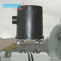
OVP2过压保护器
| 订货号: | MM-80833-00 |
| 产地: | 美国 |
| 品牌: | |
| 开发编号: | N |
| 市场价: | ¥ |
| *此产品根据配置不同价格不同 |
| *此价格为参考价格,具体价格以订单合同为准 |
- 我在现场:
- 产品视频:

- 产品描述
- 技术参数
- 技术文档
- 相关产品
- 明细价格
- 购买流程
产品描述:
OVP2 Overview
The Over-Voltage Protector design has been established since 1999 as the premier explosion-proof (Division 1) protection device for insulated joints and related applications. DEI now offers a variation of the OVP design in a molded housing, designated the OVP2, for Division 2 or ordinary locations. The OVP2 offers the same conservative design and features of the OVP, but in a lighter weight and lower cost package.
The OVP2 is UL and C-UL listed for use in Division 2 or ordinary locations, as well as CE marked as meeting the ATEX requirements for Zone 2.
Unlike "arrester" type products, the OVP2 is a solid-state switching device with full ratings for AC fault current and high levels of lightning surge current. As the device goes into conduction at low voltage, it provides much better protection than gapped devices or metal-oxide varistors.
Note: the OVP2 is not recommended where steady-state AC voltage exists between the connection points, typically induced AC voltage.
Features & Characteristics
The only fail-safe "arrester" on the market (i.e.. fails shorted).
Solid-state design eliminates arcing.
Conduction at much lower voltages than gapped arresters.
Rated for AC fault current and lightning surge current.
Suitable for submersed or above-ground locations.
UL, C-UL listed Div. 2 design, CE marked for ATEX compliance.
Corrosion-free, lightweight molded housing.
Typical Applications
Insulated Joint Protection
Airport Fueling Systems Isolation / Bonding
Decoupling Equipment Grounds
|
Specifications
Threshold Voltage (absolute)
-2/+2V (standard) -Up to -3/+1V (optional) Lightning Surge Current
100 kA crest (4 x 10 µs waveform) for 5.0 kA, 3.7KA and 2.0 kA models 75 kA crest (4 x 10 µs waveform) for 1.2 kA models
Environmental rating: IP-68 - Submersible to 2 m depth.
Hazardous (classified) areas:
Per NEC, CSA: Class I, Division 2, Groups A, B, C, D Per EN50021: Zone 2 Third-party listings & approvals:
Underwriter's Laboratories (UL) Underwriter's Laboratories - Canada (C-UL) Demko, CE Mark Dimensions & installation See OVP2 drawings in pdf format | |||||||||||||||
Technical Comparisons
Comparison of Dairyland OVP2 to Gapped Arresters
Zinc grounding cells
These cells consist of two zinc rods, with insulation material to separate them, in a conductive backfill material, packaged in a bag. The insulation or separator leaves the zinc rods reasonably close together without touching. The backfill material, such as bentonite, promotes conduction and contact with the surrounding earth, as the package is buried near the points it is connected to. A wire lead attaches each rod to a point of interest, such as across an insulated flange, or between a pipeline and ground. The concept for protection is that the zinc rods will allow separation of the two structures, and minimize the DC cathodic protection current flow under normal conditions. Under over-voltage conditions, the small separation between the rods, and the conductive backfill will allow current to flow between them, draining the unwanted current.
There are several ways in which the zinc grounding cells will not perform very well for this application. First, the package must be buried. If the application is protection of insulated joints from over-voltage (lightning, for example), and the joint is above ground, the leads that connect to the joint will be at least several feet each. Under lightning surge conditions, this affords little or no over-voltage protection to the insulated joint, as leads have inductance, which lightning sees as a high impedance, and therefore creates a large voltage drop in the leads. Lightning protection for insulated joints is best done by locating a device directly across the joint, which cannot be done with zinc grounding cells, as compared to the Dairyland OVP2.
Another electrical problem comes from AC power system fault current. Zinc grounding cells are generally not sized for handling any significant fault current.
Power laboratory testing to assure the performance of this product would be challenging, as this product is placed in service by burying in the earth, which would be difficult or impossible in a lab setting that could provide the needed values of lightning surge current or AC fault current. We have seen no test data for these products.
By separating the zinc rods in the package to achieve isolation, the question arises as to what voltage is allowed by the cell. Separation of two metallic surfaces by a medium (air, gases, solid insulation, semi-conductive backfill) has been common for over-voltage protection, but consistency of performance is an issue. Having the separation be consistent, producing a known, fixed clamping voltage is difficult if the product can vary in dimensions or construction. Consistency in over-voltage protection using a zinc grounding cell is in question, just as a spark gap arrester in air can vary during atmospheric changes due to moisture.
In addition, where the desire is to provide the lowest possible over-voltage on the structure during an event, a device should have a low impedance for conduction of current. This is not the case with a zinc grounding cell.
Dairyland OVP2 (Over-Voltage Protector 2)
As a comparison to the above description, consider the characteristics of the solid-state OVP2. It is a blocking device in the normal mode. For all signals including DC (cathodic protection) current, it presents a very high impedance up to several volts, then appears as a short circuit for disturbances. When the event is over, the device automatically reverts to blocking DC current. There is no internal gap in the device, so over-voltage clamping occurs at a very low voltage - much lower than any other technology. Consistency in performance is assured through the use of tested power semiconductor components. The device has been designed so that it will even fail as a short circuit if exposed to currents beyond the rating, providing a fail-safe nature. The OVP2 has been tested in a power laboratory and is rated for lightning surge current and AC fault current.
Comparison of Dairyland OVP2 to spark gap arresters
Arrester:
Typical terms: gas tube arrester, spark-gap arrester
Typical terms: gas tube arrester, spark-gap arrester
General Information
When the voltage across a spark gap arrester gets high enough, an arc bridges the two electrodes, establishing a current path. Spark gaps are designed to limit the voltage due to transient conditions, such as caused by lightning.
When the voltage across a spark gap arrester gets high enough, an arc bridges the two electrodes, establishing a current path. Spark gaps are designed to limit the voltage due to transient conditions, such as caused by lightning.
Most, if not all, spark gaps used in the cathodic protection (CP) industry are not designed to carry AC fault current, so they should only be used in applications where the breakdown voltage of the spark gap to AC voltage is above any peak AC voltage that might be expected. (Most other arrester products are also not designed to carry AC fault current.) From reviewing data sheets of commonly used spark gaps, the AC breakdown voltage is typically from several hundred to about one thousand volts.
A common application in the CP industry is that of providing over-voltage protection for insulated joints in pipelines carrying flammable materials. Insulated joints in such pipelines are generally classified as a Class I, Division 2 hazardous. When these pipelines are in the same corridor as electric power transmission lines, the AC voltage that can be imposed on a pipeline due to a line-to-ground fault at a nearby transmission tower, can be significantly higher than the AC breakdown voltage of the protective device at a nearby, or even fairly remote, insulated joint; thereby allowing significant AC fault current to flow through the protective device. For this reason, the U.S. Pipeline Safety Regulations (which regulate the pipeline industry in the U.S.), requires that insulated joints in pipelines be protected, and that they be protected against damage due to lightning and AC fault currents. (Section 192.467 (e) and (f) of these regulations.)
During lightning conditions, typical spark gaps have a breakdown voltage ranging from several hundred to over several thousand volts. These arresters have lightning current ratings from 30,000 to 100,000A peak which cover virtually all requirements.
It should be recognized that there is a very significant difference between a peak lightning current of some value versus an AC current of the same value. Lightning current is extremely short in duration relative to even 1/2 cycle of AC current; hence, there is very significantly more energy associated with AC fault current than with lightning current. A single lightning stroke reaches its peak current and is dissipated within about 50 microseconds whereas a typical AC fault will not be cleared until at least 3 cycles or about 50,000 microseconds. Spark gap arresters, and most other conventional lightning arresters, are not capable of handling the significantly higher energy associated with even very low levels of AC fault current.
Another key factor in insulated joint applications is the type of insulated joint being protected. In the Western hemisphere, the most common insulated joint is one that is field assembled using bolted flanges and insulation kits. Although voltage breakdown values are published for the insulation material used in these kits, no manufacturer of these kits provides a voltage withstand value for the finished insulated joint; namely, because there are too many variables which are out of their control. Further, due to the undesirable electrical geometry of most bolted type insulated joints (i.e., sharp corners, minimal distance between flanges, etc.) there is minimal correlation between the actual voltage withstand capability between adjacent flanges and the voltage breakdown values of the insulation material used in the insulation kit.
For the above reasons, when providing over-voltage protection for typical bolted-type insulated joints, the optimum over-voltage protector will begin providing protection at the lowest allowable voltage level. In most applications, this is just above the maximum voltage expected across the insulated joint, which is typically the DC cathodic protection voltage.
By comparison, monolithic (i.e, factory fabricated) insulated joints are available with known, and considerably higher, voltage withstand values than most bolted insulated joints. Electrically, these joints are superior and accordingly are significantly more expensive. They are still subject to over-voltage failure.
Dairyland OVP2 (Over-Voltage Protector 2):
For CP applications where the absolute voltage (i.e., DC plus peak AC) between the points to be protected is within the blocking voltage rating of the OVP2, the OVP2 is recommended. Its characteristics and ratings relative to typical arrester products are described below. If the absolute voltage between the planned connection points is greater than the capability of the OVP2, then the DEI solid state Polarization Cell Replacement product, described in the following section, should be considered.
For CP applications where the absolute voltage (i.e., DC plus peak AC) between the points to be protected is within the blocking voltage rating of the OVP2, the OVP2 is recommended. Its characteristics and ratings relative to typical arrester products are described below. If the absolute voltage between the planned connection points is greater than the capability of the OVP2, then the DEI solid state Polarization Cell Replacement product, described in the following section, should be considered.
The OVP2 is a solid-state, bi-directional, over-voltage protection device that blocks both AC and DC up to a predetermined voltage threshold. Standard threshold levels are -2/+2 volts, with various combinations up to -4/+1 volts available upon request. The instant the voltage attempts to exceed the threshold value selected, voltage clamping begins and current is readily allowed to flow through the OVP2.
The OVP2 has the following standard ratings:
Blocking threshold voltage: -2/+2V Standard
Lightning current: 100,000A peak (4 x 10 waveform)
AC Fault Current (30 cycles): 3,700A (50/60 Hz)
Blocking threshold voltage: -2/+2V Standard
Lightning current: 100,000A peak (4 x 10 waveform)
AC Fault Current (30 cycles): 3,700A (50/60 Hz)
There is no steady-state AC current rating because the OVP2 is not recommended where the steady-state AC voltage will put the OVP2 in continual conduction. This would cause partial rectification of the AC waveform and could adversely affect CP levels.
Instead of waiting until the voltage is hundreds to several thousand of volts, the OVP2 begins voltage clamping just above the blocking threshold voltage, a significant advantage for personnel safety and for applications such as insulated joint protection. There is no arcing within the OVP2 since it uses all solid-state components. Voltage clamping is instantaneous. Under AC fault conditions, the OVP2 will limit the voltage to less than 10 volts peak under maximum rated fault current. Under lightning current conditions, the OVP2 will limit the voltage directly across its terminals to less than 100 volts at 100,000 amperes peak. When taking into account the effect of lead induced voltage, the voltage across a typical insulated joint under maximum rated lightning current would be on the order of 1250 volts. The OVP2 is designed to be installed with the shortest possible lead length to minimize the voltage drop in the lead caused by L(di/dt) effect, where L is the lead inductance per unit length and di/dt is the rate of change of current, which is extremely high for lightning. Most other manufacturers of protective devices do not mention the very adverse effect of lead length, a point that DEI highly emphasizes in its literature. For most insulated joint applications, the OVP2 can, and should, be installed with a total lead length of about 6” (150 mm). For more information on this subject, request DEI’s article on the effects of lead length.
An important safety feature regarding the design of the OVP2, is that it is “fail-safe.” If exposed to current values beyond rating so that failure occurs, failure will occur in the shorted mode (i.e., fail as a short circuit). In the shorted mode, the OVP2 still meets all current ratings but it will not be blocking DC current. This assures over-voltage protection and personnel safety at all times. Most known spark gap and other lightning arresters used in the CP industry will fail as an open circuit when tested to failure.
The OVP2 is UL listed for Class 1, Division 2 hazardous locations, Groups B, C, and D and is packaged in a NEMA 6P (IP68) explosion-proof, submersible enclosure.
Summary of benefits of the OVP2 versus most lightning arresters:
Much lower threshold voltage.
AC fault current rated.
Clamps voltage to much lower levels.
Fail-safe.
Known, fixed parameters.
UL listed for Class I, Div. 1 & 2 hazardous locations.
UL listed as an over-voltage protective device for lightning current.
Explosion proof, NEMA 6P (IP68) enclosure.
DEI has test data that shows the total voltage drop of the OVP2 plus leads. Other devices only publish data regarding the product alone.
技术参数:

泰亚赛福作为众多知名品牌的合作伙伴,优惠的价格+完善的售后服务体系向您提供产品。font>

泰亚赛福作为众多知名品牌的合作伙伴,优惠的价格+完善的售后服务体系向您提供产品。font>
技术文档:

泰亚赛福作为众多知名品牌的合作伙伴,优惠的价格+完善的售后服务体系向您提供产品。font>
- 在线浏览:
- 文档下载:

泰亚赛福作为众多知名品牌的合作伙伴,优惠的价格+完善的售后服务体系向您提供产品。font>
相关产品:

泰亚赛福作为众多知名品牌的合作伙伴,优惠的价格+完善的售后服务体系向您提供产品。font>
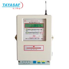 DT5-GX电压监测统计仪订货号:MM-01179-00
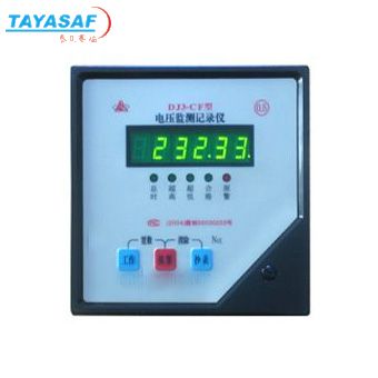 DJ3-CF电压监测记录仪订货号:MM-21325-00
 交流电压传感器订货号:MM-80815-00
 高电压检测仪订货号:MM-80811-00
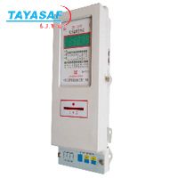 DT1-GD电压监测统计仪订货号:MM-80812-00
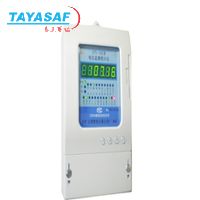 DT1-GK电压监测统计仪订货号:MM-80813-00
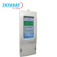 DT1-G电压监测统计仪订货号:MM-80814-00
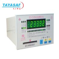 DT2-CD电压监测统计仪订货号:MM-80816-00
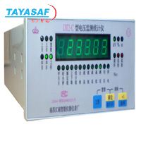 DT2-C电压监测统计仪订货号:MM-80817-00
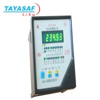 DT3-CF电压监测统计仪订货号:MM-80818-00
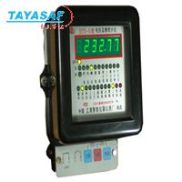 DT3-G电压监测统计仪订货号:MM-80819-00
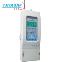 DT6-GP电压监测统计仪订货号:MM-80820-00

泰亚赛福作为众多知名品牌的合作伙伴,优惠的价格+完善的售后服务体系向您提供产品。font>
明细价格:

泰亚赛福作为众多知名品牌的合作伙伴,优惠的价格+完善的售后服务体系向您提供产品。font>
| 定货号 | 产品名称 | 规格配置 / 简介 | 市场价/(会员价) |
|---|---|---|---|
| MM-80833-00 | OVP2过压保护器 | /() |

泰亚赛福作为众多知名品牌的合作伙伴,优惠的价格+完善的售后服务体系向您提供产品。font>
购买流程:

泰亚赛福作为众多知名品牌的合作伙伴,优惠的价格+完善的售后服务体系向您提供产品。font>
①购买产品:点击“生成订单”→填写产品数量、联系方式并提交→会员顾问订单处理→合同签订。
②咨询产品:请联系会员顾问或致电会员客服电话。
③如果您还不是我们的会员,请先注册。
④最小起订数量:1
注意:本产品唯一个人现金委托收款人,如汇入其它个人账户本公司不承担任何责任
维护担当:
上线时间:
投诉电话:13801126385 13911302309
②咨询产品:请联系会员顾问或致电会员客服电话。
③如果您还不是我们的会员,请先注册。
④最小起订数量:1
注意:本产品唯一个人现金委托收款人,如汇入其它个人账户本公司不承担任何责任
维护担当:
上线时间:
投诉电话:13801126385 13911302309
联系方式
电话北京:400-000-1836 分机 或拨0转总机
上海:021-54248686 分机 或拨0转总机
上海:021-54248686 分机 或拨0转总机
传真北京:010-84852750/84854139
上海:021-64418200
上海:021-64418200

泰亚赛福作为众多知名品牌的合作伙伴,优惠的价格+完善的售后服务体系向您提供产品。font>
您最近浏览的商品


 美国MI
美国MI


