
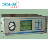
Mod. Enox DPB红外线分析仪
| 订货号: | MM-40113-00 |
| 产地: | 意大利 |
| 品牌: | |
| 开发编号: | N |
| 市场价: | ¥ |
| *此产品根据配置不同价格不同 |
| *此价格为参考价格,具体价格以订单合同为准 |
- 我在现场:
- 产品视频:

- 产品描述
- 技术参数
- 技术文档
- 相关产品
- 明细价格
- 购买流程
产品描述:
Imtroduction
The analyzer is housed in a steel 19” rack 3 vertical unit high.
On the rear panel are located the connector for digital and analogical input and output, the filtered power connect with switch and fuses and the fittings for sample inlet and outlet. Inside the housing is located a low flow detector and optionally a diaphragm pump and an AISI solenoid valve for automatic zero calibration and an electrochemical cell for the O2 simultaneously measure in the sample.
In the front panel are present a 16 keys keyboard, a fast to be check and replace fine filter with the big back lighted LCD display
Application
The analyzer can be used for gas measuring in a wild range of industrial applications:
Combustion control
Measuring of emissions of boilers, furnaces, domestic and industrial incinerators, cement, furnaces, etc.
Process gas
Monitoring of emissions from engines and turbine with NOx lowering systems (SCR – DENOX – LENOX etc…)
Analysis of gases from
Air quality in green houses, tunnels, parking
Analysis of protection atmosphere
Principle of operation
A wide band infrared radiation is emitted by a non metallic, high stability source.
For each measured gas this radiation is brought alternatively through an interferential filter and a filter with a glass cell (GFC) filled with high partial pressure of the gas to be analyzed.
A suitable optical system drives the IR radiation inside the analysis chamber and then to the detector which receives and amplifies alternatively the two signals: one is the measure, the other is the reference. The gas concentration is proportional to the difference of the two signals.
Gases which may have a cross sensitivity with the measured gas, generate the same variation of the measure and reference signals. Therefore the measure is not affected.
Technical description
The Enox multigas analyzer is an industrial photometer based on the non dispersive photometry in the infrared, for the contemporary measure of several gases.
The main feature of this enhanced analyzer model DPB (double path beam) is to have a long optical path to obtain to very high sensitivity to guarantee the declared performance even on the very low ranges requested from the lower and lower emissions limit imposed.
The mainly pulse to follow and reach this solution has been driven from the necessity to develop an NDIR NO (nitrogen oxide) analyzer with performance comparable with the expensive ones normally used where the emission limits are about some tens vpm.
The technology which has been used is based on correlation filters (GCF) and optical non dispersive absorption (DOAS). A high stability sensor, working at a very low temperature (-35 °C) and the GFC technology ensure a nearly fully immunity to cross sensitivity, high stability and sensitivity.
The measuring principle, the optical bench and the automatic and accurate compensation of the variations of room temperature enable to avoid the expensive and complicated automatic calibrations, which are always possible.
A large back lighted graphic display continuously supplies the value of the measured gases (including a large bar graph), the alarms, the service requirements, the faults, separated for each gas and the alarms from the sampling system. All alarms have the acknowledgement routine. All anomaly messages are reported on the display for the immediate knowledge of what has gone wrong. Relays contacts enable all the diagnostic to be retransmitted.
This instrument has been drawn to be user friendly and reduce as much as possible the costs of the analysis system in which it will be used. The analyzer can manage a multiplexing CEM up to four emission point and can be directly connected to a P.C. provided with a special software, named DAS-DAC, for data acquisition monitoring and reporting..
|
Technical specifications | ||
|
Measured components |
Lowest ranges:
1. CO 0…10 ppm
2. CO2 0…10 ppm
3. NO 0…50 ppm
4. SO2 0…400 ppm
5. CH4 0…100 ppm
6. O2 0…25% in volume
Highest ranges:
100% or saturation. |
|
|
Measure units |
vpm, mg/m3, mg/Nm3, % |
|
|
Display |
240X128 pixel, graphic, back lighted LCD, tunable contrast |
|
|
Keyboard |
16 keys membrane |
|
|
Analogical Output |
N. 4 4-20 mA linear isolated. Max load 500 ohm. |
|
|
Digital Output |
RS 232, RS 485, Modbus |
|
|
Flow control on sample |
Continuous on flow lower than 0.5 l/min |
|
|
Digital Output |
N. 2 contacts settable alarms on each measure, except oxygen
N. 1 contact service for each measure, except oxygen
N. 1 contact fault for each measure, except oxygen, and flow fault
N. 1 contact for calibration
N. 2 contacts for solenoid valve, in case of external calibration (24 Vcc 50 mA) |
|
|
Digital Input (12 Vcc 100 mA) |
N. 1 Distant calibration
N. 1 sampling system fault
N. 4 stack currently on measure (for scansions)
N. 4 low cylinder pressure |
|
|
Warm up time |
’15
45’ best performance |
|
|
Zero calibration. |
Automatic with ambient air or nitrogen. Tunable frequency and duration |
|
|
Span calibration |
Automatic not necessary. Tunable frequency and duration |
|
|
Drift |
Negligible with automatic zero calibration:
· < 2% of lowest range without automatic zero calibration
· Ambient temperature: negligible continuously compensated
· Atmospheric pressure: settable
· zero: none
· span about 1% of measured value for 1% of atmospheric pressure change |
|
|
Response time (T90) |
Depending on mobile average set |
|
|
Noise |
</= 1% of lowest range |
|
|
Mobile average |
Tunable between 0 ….600” |
|
|
Ambient temperature |
For measure +5…+35°C
For stocking and transport -10…+55°C |
|
|
Moisture |
<90% RH not condensing |
|
|
Panel filter |
Retention: 1 micron |
|
|
Sample gas status |
pressure 20…80 mbar
flow 30…180 Nl/h
temperature +5…+50°C
dew point at least 5°C under ambient temperature |
|
|
Protection |
IP20 |
|
|
Power |
115-230 V AC +/-10% about 70 VA |
|
|
Dimensions |
450X132x380 mm |
|
|
Weight |
kg. 12 |
|
技术参数:

泰亚赛福作为众多知名品牌的合作伙伴,优惠的价格+完善的售后服务体系向您提供产品。font>

泰亚赛福作为众多知名品牌的合作伙伴,优惠的价格+完善的售后服务体系向您提供产品。font>
技术文档:

泰亚赛福作为众多知名品牌的合作伙伴,优惠的价格+完善的售后服务体系向您提供产品。font>
- 在线浏览:
- 文档下载:

泰亚赛福作为众多知名品牌的合作伙伴,优惠的价格+完善的售后服务体系向您提供产品。font>
相关产品:

泰亚赛福作为众多知名品牌的合作伙伴,优惠的价格+完善的售后服务体系向您提供产品。font>
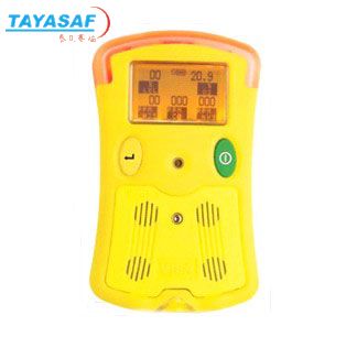 VISA手持式复合气体检测仪订货号:MM-00262-00
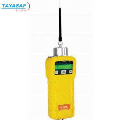 VRAE五合一气体检测仪[PGM-7800]订货号:MM-00888-00
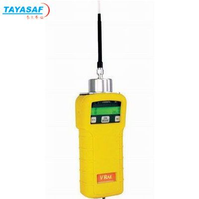 VRAE五合一气体检测仪[PGM-7840]订货号:MM-00890-00
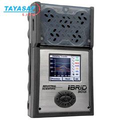 美国英思科MX6复合式多气体检测仪订货号:MM-01046-00
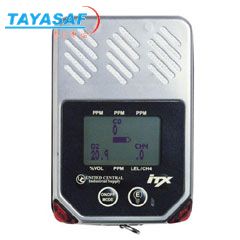 iTX 复合式气体检测仪订货号:MM-01709-00
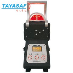 BM25复合式气体检测仪订货号:MM-01724-00
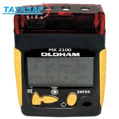 MX2100复合式气体检测仪订货号:MM-01705-00
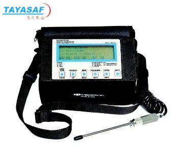 IQ-1000万用气体检测仪订货号:MM-02603-00
 IQ-1000苯乙烯气体检测仪订货号:MM-08222-00
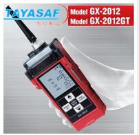 日本理研复合气体检测仪GX-2012订货号:TA-01459-00
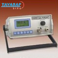 KG850便携式气体分析仪订货号:MM-84962-00
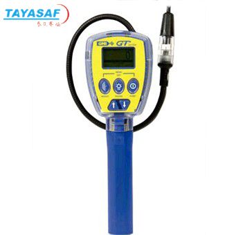 GT41可燃气体检测仪订货号:TA-00094-00

泰亚赛福作为众多知名品牌的合作伙伴,优惠的价格+完善的售后服务体系向您提供产品。font>
明细价格:

泰亚赛福作为众多知名品牌的合作伙伴,优惠的价格+完善的售后服务体系向您提供产品。font>
| 定货号 | 产品名称 | 规格配置 / 简介 | 市场价/(会员价) |
|---|---|---|---|
| MM-40113-00 | Mod. Enox DPB红外线分析仪 | /() |

泰亚赛福作为众多知名品牌的合作伙伴,优惠的价格+完善的售后服务体系向您提供产品。font>
购买流程:

泰亚赛福作为众多知名品牌的合作伙伴,优惠的价格+完善的售后服务体系向您提供产品。font>
①购买产品:点击“生成订单”→填写产品数量、联系方式并提交→会员顾问订单处理→合同签订。
②咨询产品:请联系会员顾问或致电会员客服电话。
③如果您还不是我们的会员,请先注册。
④最小起订数量:1
注意:本产品唯一个人现金委托收款人,如汇入其它个人账户本公司不承担任何责任
维护担当:
上线时间:
投诉电话:13801126385 13911302309
②咨询产品:请联系会员顾问或致电会员客服电话。
③如果您还不是我们的会员,请先注册。
④最小起订数量:1
注意:本产品唯一个人现金委托收款人,如汇入其它个人账户本公司不承担任何责任
维护担当:
上线时间:
投诉电话:13801126385 13911302309
联系方式
电话北京:400-000-1836 分机 或拨0转总机
上海:021-54248686 分机840 / 211 或拨0转总机
上海:021-54248686 分机840 / 211 或拨0转总机
传真北京:010-84852750/84854139
上海:021-64418200
上海:021-64418200

泰亚赛福作为众多知名品牌的合作伙伴,优惠的价格+完善的售后服务体系向您提供产品。font>
品牌简介
您最近浏览的商品


 意大利FER
