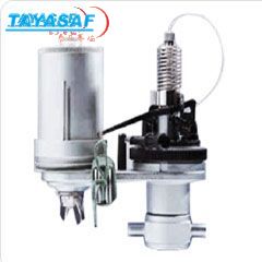
Leutert engine indicators are used on diesel engines, gas engines, air compressors, pumps, etc.
A metal stylus draws a clear pressure-path diagram which records the pressure curve within the engine cylinders as influenced by the piston stroke. The recording drum can be moved by means of a string, which is pulled manually or by the engine. If the drum is driven by the engine, the diagram may be planimetered.
Our indicators are designed to cover various ranges of
speed and rates of pressure-change.
It will always be advisable to operate with small diagrams as far as possible, in consideration of the oscillating masses. In doubtful cases it is suggested to forward particulars of the operating conditions, and on orders to give particulars regarding kind of engine, pressures to be measured, engine stroke and r.p.m.
The selection of the correct indicator size depends not only on the r.p.m but also on the rate of pressure rise at time unit dp/dt. If the above stated limit values are exceeded, the resulting acceleration would cause too high an indication of pressure. Size of piston and spring are selected such that the maximum natural frequency is attained. With regard to the accelerations, for best results the diagram length should be progressively reduced as the r.p.m. approaches the designed maximum of the indicator.
• Individually calibrated high accuracy heat treated
springs
• Unchanged, rugged and proven reliable Maihak
design
• Easy and simple operation by unskilled operator
• Cheapest way to analyze your engine
• Ready-to-use equipment
Measuring range : see spring table below
Engine range : up to n = 300 rpm or
max. dp/dt = 9 x 10³ bar/sec
Max. diagram : 50 mm/80 mm (height/length)
Drum diameter : 50 mm
Paper size : 180 mm x 65 mm
Dimensions : 165 mm x 130 mm x 90 mm
Weight : 1.5 kg (without wooden box)
4.4 kg (with wooden box)
Standard connection : W 27 x 1/10��
1 wooden box, 1 spring, 1 measuring scale, 1 block
indicator paper each 40 sheets, 1 cord tightening
hook, 1 oil can for piston and links, 1 screw driver,
1 flat plier, 1 hollow spanner, 1 cylinder cleaner,
1 stand for instrument, 1 bundle indicator cord,
1 tube incl. 5 recording pencils, 1 vacuum washer,
1 operating instructions
Table of Indicator Springs Type 50
Piston Scale Max. Pressure Spring-No. Part-No.
1/10 0.35 mm/bar 140 bar 50 / 14 bar 4651.0.71.14000
1/10 0.30 mm/bar 160 bar 50 / 16 bar 4651.0.71.15000
1/10 0.25 mm/bar 200 bar 50 / 20 bar 4651.0.71.16000
1/10 0.20 mm/bar 250 bar 50 / 25 bar 4651.0.71.17000
1/10 0.15 mm/bar 300 bar 50 / 30 bar 4651.0.71.18000


 TH200����ȦȦ�������������ţ�MM-00385-00
 PAK-210ESD�����װ�����ţ�MM-00784-00
 PAK-212����ϵͳ�����װ�����ţ�MM-00789-00
 PSK-310ESDϵͳ������װ�����ţ�MM-00877-00
 ZJA-30��Ч˫��������ͻ������ţ�MM-00881-00
 PSK-312ESD����ϵͳ������װ�����ţ�MM-00908-00
 FHV-100�۽�ʽ���ͻ������ţ�MM-00955-00
 5900��ͳ�̶����ܷ����������ţ�MM-04152-00
 5904��ͳ�̶����ܷ����������ţ�MM-04156-00
 C0510���º��²������ţ�MM-10487-00
 C0515���º��²������ţ�MM-10502-00
 HX-85��ѹ�����������ţ�TA-00324-00


 �¹�����