|
Specifications |
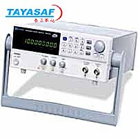
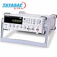
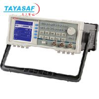
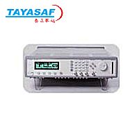
Model 4084 |
|
Function Generator |
|
Frequency Characteristics |
|
|
Frequency Range |
|
|
|
Sine |
1µHz ~ 20MHz |
|
Square |
1µHz ~ 20MHz |
|
All Other Waveforms |
1µHz ~ 100kHz |
|
Frequency Stability |
±1 × 10⁻⁶ (22°C ± 5°C) |
|
Resolution |
1µHz |
|
Frequency Accuracy |
≤ ±5 × 10⁻⁶ (22°C ± 5°C) |
|
Data entry Units |
s, ms, Hz, kHz, MHz |
|
Waveform Characteristics |
|
|
Main waveforms (Sine, square) |
|
|
|
Amplitude resolution |
12 bits |
|
Sample Rate |
200MSa/s |
|
Sine |
|
|
|
Harmonic Distortion of Sine Wave* |
≤ -50dBc (frequency ≤ 5MHz)
≤ -45dBc (frequency ≤ 10MHz)
≤ -40dBc (frequency ≤ 20MHz) |
|
Total Harmonic Distortion* |
0.1% (20Hz ~ 100kHz) |
|
Square |
|
|
|
Rise and fall time* |
≤ 15ns |
|
* = Note: Test conditions for harmonic distortion, sine distortion, rise/fall time Output Amplitude 2Vp-p, Environmental temperature: 25°C ± 5°C |
|
|
Other built-in waveforms: |
|
|
|
27 build-in standard and complex waveforms. |
Sine, Square, Triangle, Positive Ramp, Falling Ramp, Noise, Pulse, Positive Pulse, Negative Pulse, Positive DC, Negative DC, Stair wave, Coded Pulse, Full wave rectified, Half-wave rectified, Sine transverse cut, Sine vertical cut, Sine phase modulation, Logarithmic, Exponential, Half-round, sin x/x, Square root, Tangent, Cardiac, Earthquake, Combination |
|
Waveform Length |
4096 dots |
|
Amplitude Resolution |
10 bits |
|
Pulse Wave |
|
|
|
Duty Cycle |
0.1% ~ 99.9% (below 10kHz), 1% ~ 99% (10kHz ~ 100kHz) |
|
Rise/Fall Time |
≤ 100ns (Duty Cycle 20%) |
|
DC signal characteristics |
|
|
|
DC range |
≤ 10mV - 10V (high impedance) |
|
DC Accuracy |
≤ ±5% of setting +10mV (high impedance) |
|
Amplitude Characteristics |
|
|
Amplitude Range |
2mV ~ 20Vpp (open circuit), 1mV ~ 10Vpp (50Ω) |
|
Resolution |
2µVpp (open circuit), 1µVpp (50Ω) |
|
Accuracy |
±1% + 0.2mV (sine wave relative to 1kHz) |
|
Stability |
±0.5% / 3 hours |
|
Flatness |
|
|
|
For amplitude ≤ 2Vpp |
±3% (frequency ≤ 5MHz), ±10% (5MHz < frequency ≤ 40MHz) |
|
For amplitude > 2Vpp |
±5% (frequency ≤ 5MHz), ±10% (5MHz < frequency ≤ 20MHz) |
|
Output Impedance |
50Ω |
|
Output Units |
Vpp, mVpp, Vrms, mVrms, dBm |
|
DC Offset Characteristics |
|
|
Offset Range (open circuit) |
±10Vpk ac + dc (Offset ≤ 2 × peak-to-peak amplitude) |
|
Offset Resolution |
2µV (open circuit), 1µV (50Ω) |
|
Offset Error |
±5% of setting + 10mV (Ampl. ≤ 2Vpp into open circuit)
±5% of setting + 20mV (Ampl. > 2Vpp into open circuit) |
|
AM Characteristics |
|
|
Carrier Waveforms |
sine or square |
|
Modulation Source |
internal or external |
|
Internal Modulating Waveform |
sine, square, triangle, rising/falling ramp |
|
Frequency of modulating signal |
100µHz ~ 20kHz |
|
Distortion |
≤ 2% |
|
Modulation Depth |
1% ~ 120%
1% ~ 80% (frequency > 40MHz, Ampl > 2Vpp into open circuit) |
|
Modulation Error |
±5% + 0.2% (100µHz < frequency ≤ 10kHz)
±10% + 2% (10kHz < frequency ≤ 20kHz) |
|
Max. Amplitude of ext. input signal |
3Vp-p (-1.5V ~ +1.5V) |
|
FM Characteristics |
|
|
Carrier Waveforms |
sine or square |
|
Modulation Source |
internal or external |
|
Internal Modulating Waveform |
sine, square, triangle, rising/falling ramp |
|
Frequency of modulating signal |
100µHz ~ 10kHz |
|
Deviation |
Max. 50% of carrier frequency for internal FM
Max. 100kHz (carrier frequency ≥ 5MHz) for external FM, with input signal voltage 3Vp-p (-1.5V ~ +1.5V) |
|
FSK Characteristics |
|
|
Carrier Waveform |
sine or square |
|
Control Mode |
internal or external trigger (external: TTL level, low level F1, high level F2) |
|
FSK Rate |
0.1ms ~ 800s |
|
PSK Characteristics |
|
|
Carrier Waveform |
sine or square |
|
PSK |
Phase 1 (P1) and Phase 2 (P2), range: 0.0 ~ 360.0° |
|
Resolution |
0.1° |
|
PSK rate |
0.1ms ~ 800s |
|
Control Mode |
internal or external trigger (external: TTL level, low level P1, high level P2) |
|
Burst Characteristics |
|
|
Carrier Waveform |
sine or square |
|
Burst Counts |
1 ~ 10000 cycles |
|
Time interval between bursts |
0.1ms ~ 800s |
|
Control Mode |
internal, single or external gated trigger |
|
Frequency Sweep Characteristics |
|
|
Carrier Waveform |
sine or square |
|
Sweep Time |
1ms ~ 800s (linear), 100ms ~ 800s (log) |
|
Sweep Mode |
Linear or Logarithmic |
|
Start/Stop Frequency |
same as frequency range of sine and square |
|
External trigger signal frequency |
DC ~ 1kHz (linear) DC ~ 10Hz (log) |
|
Control Mode |
Internal or external trigger |
|
Inputs/Outputs |
|
|
Main OUTput |
|
|
|
Impedance |
50Ω |
|
Protection |
Short circuit and overload protected |
|
Amplitude |
5Vp-p ± 5% |
|
Output Impedance |
600Ω |
|
|
Output MOD OUT |
|
|
|
Frequency |
100Hz ~ 20kHz |
|
Waveform |
sine, square, triangle, rising/falling ramp |
|
Amplitude |
5Vp-p ± 5% |
|
Output Impedance |
600Ω |
|
Modulation IN |
3 Vpp = 100% Modulation |
|
External Input Trig / FSK / Burst |
Level - TTL |
|
State Storage Characteristics |
|
|
Storage Parameters |
frequency, amplitude, waveform, DC offset values, modulation parameters |
|
Storage Capacity |
10 user configurable stored states |
|
Universal Counter |
|
Frequency Range |
|
|
Frequency Measurement |
1Hz ~ 100MHz |
|
Totalize mode |
50MHz max |
|
Input Characteristics |
|
|
Sensitivity |
|
|
|
Input attenuator disabled |
50mVrms (f: 10Hz ~ 50MHz), 100mVrms
(f: 1Hz ~ 100MHz) |
|
Input attenuator enabled |
0.5Vrms (f: 10Hz ~ 50MHz), 1Vrms
(f: 1Hz ~ 100MHz) |
|
Max. Input Voltage Allowed |
100Vp-p (f ≤ 100kHz), 20Vp-p (1Hz ~ 100MHz) |
|
Input Impedance |
R > 500kΩ, C < 30pF |
|
Coupling |
AC |
|
Waveform |
sine or square |
|
Low Pass Filter |
cut off frequency about 100kHz (with internal attenuation: ≤ -3dB) with external attenuation: ≥ -30 dB (f > 1MHz) |
|
Gate Time Setting |
10ms ~ 10s continuously adjustable |
|
Display Bits |
8 (for gate Time > 5s) |
|
Totalize Capacity |
≤ 4.29 × 10⁹ |
|
Control Mode |
manual or external gate control |
|
Accuracy |
time base error ± trigger error (when signal SNR > 40dB, trigger error ≤ 0.3) |
|
Time base |
|
|
|
Frequency |
10MHz |
|
Stability |
±1 × 10⁻⁶ (22°C ± 5°C) |
|
General |
|
Power Supply |
198 ~ 242V or 99 ~ 121V, Frequency: 47 ~ 63Hz |
|
Power Consumption |
< 35VA |
|
Operating Temperature |
0° to +40 °C |
|
Operating Humidity |
80% R.H |
|
Storage Temperature |
-40°C to 70°C |
|
Dimensions (W × H × D) |
10” x 3.93” x 14.56”
(255 mm × 100 mm × 370 mm) |
|
Weight |
6.6 lbs, (3 kg) |
|
Remote Interface |
RS232 |
|
Safety designed to |
EN61010 |
|
EMC tested to |
EN55022, EN55024, EN61326, EN60100 |

 泰亚赛福 ―― 世界领先的检测仪器集成供应商


 您当前的位置:
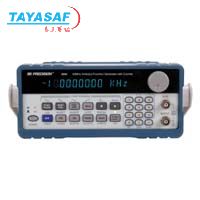

 加入对比
加入对比