|
Specifications |
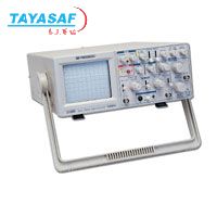
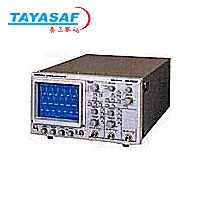
Model 2190B |
|
VERTICAL AMPLIFIERS (CH 1 and CH 2) |
|
Sensitivity |
5mV/div to 5V/div. 1 mV/div to 1V/div (at X5 MAG) |
|
Attenuator |
10 calibrated steps in 1-2-5 sequence.
Vernier control provides fully adjustable sensitivity between steps, adjustment range 1/1 to 1/2.5 |
|
Accuracy |
+-3% (+-5% at X5 MAG) |
|
Input Impedance |
1MW+ 3% |
|
Input Capacitance |
25 pF +- 10pF |
|
Frequency Response |
DC: DC to 100 MHz (-3 dB) on 10mV/Div setting |
|
X5 MAG |
DC to 20 MHz (-3 dB) |
|
AC |
10Hz to 100 MHz (-3 dB) |
|
Rise Time |
3.5 ns (Overshoot <=5%) |
|
Signal Delay Time |
Variable |
|
Square Wave Characteristics |
Overshoot less than 5%, 10mV/div range
Other ranges within 5% additional |
|
Maximum Input Voltage |
400V (DC + AC peak) |
|
VERTICAL AMPLIFIERS |
|
Operating Modes |
CH 1, CH 2, Dual, Add |
|
Delay Time Between Channels |
Within 1 ns between CH 1 and CH 2 |
|
Crosstalk |
30:1 at 100 kHz |
|
SWEEP SYSTEM |
|
Operating Modes |
|
|
A |
A sweep |
|
B |
Delayed B sweep |
|
B TRIGGERED |
B sweep triggered after delay |
|
A Time Base |
|
|
Sweep Mode |
Auto, normal |
|
Sweep Time: |
5s to 20ns/div., 23 steps in 1-2-5 sequence with variable control |
|
Accuracy |
+-3% |
|
Hold Off Time |
Continuously variable. Adjustment range from normal to 1,5 times the sweep time |
|
B Time Base |
|
|
Delay Method |
Continuous delay. Triggered delay |
|
Sweep Time |
20ns to 0.5s/div., 23 steps in 1-2-5 sequence |
|
Accuracy |
+-3% |
|
Hold Off Time |
Continuously variable. Adjustment range from normal to 1.5 times the sweep time |
|
B Time Base |
|
|
Delay Method |
Continuous delay. Triggered delay |
|
Sweep Time |
20 ns. to 0.5s/div., 23 steps in 1-2-5 sequence |
|
Accuracy |
+-3% |
|
Delay Time |
Start point: 0.5 div to + 0.3 div.
End point: 10 div + 1 div |
|
Delay Jitter |
Within 1/10,000 of full scale sweep time |
|
TRIGGERING |
|
A Trigger |
|
|
Source |
CH 1, CH 2, LINE, EXT |
|
Sensitivity |
30Hz to 110 MHz |
|
TV-V |
20Hz - 30kHz |
|
TV-H |
3 kHz - 100 kHz |
|
Slope |
+ or - |
|
B Trigger |
The A trigger is also the B trigger |
|
EXTERNAL TRIGGER |
|
Input Impedance |
1 m , 30 pF |
|
Maximum Input Voltage |
300V (DC + AC peak) |
|
HORIZONTAL AMPLIFIER |
|
X-Y Mode |
X Axis = CH 1, Y Axis = CH 2 |
|
Sensitivity |
5 mV/div to 5 V/div, CH 1 and CH 2 |
|
Accuracy |
+- 3% calibrated position, +-6% using x10 MAG |
|
Frequency Response |
DC: DC to 100 MHz (-3 dB) |
|
X5 MAG |
DC to 20 MHz (-3 dB) |
|
AC |
10 Hz to 100 MHz (-3 dB) |
|
Rise Time |
3.5 ns (Overshoot <=5%) |
|
Signal Delay Time |
Variable |
|
Square Wave Characteristics |
Overshoot less than 5%, 10 mV/div range |
|
|
Other ranges within 5% additional |
|
Maximum Input Voltage |
400V (DC + AC peak) |
|
VERTICAL AMPLIFIERS |
|
Operating Modes |
CH 1, CH 2, Dual, Add |
|
Delay Time Between Channels |
Within 1 ns between CH 1 and CH 2 |
|
Crosstalk 30:1 at 100 kHz |
|
|
SWEEP SYSTEM |
|
Operating Modes |
|
|
A |
A sweep |
|
B |
Delayed B sweep |
|
B TRIGGERED |
B sweep triggered after delay |
|
A Time Base |
|
|
Sweep Mode |
Auto, normal |
|
Sweep Time: |
5s to 20ns/div., 23 steps in 1-2-5 sequence with variable control |
|
Accuracy |
+-3% |
|
Hold Off Time |
Continuously variable. Adjustment range from normal to 1.5 times the sweep time |
|
B Time Base |
|
|
Delay Method |
Continuous delay. Triggered delay |
|
Sweep Time |
20ns. to 0.5s/div., 23 steps in 1-2-5 sequence |
|
Accuracy |
+-3% |
|
Delay Time |
Start point: 0.5 div to + 0.3 div.
End point: 10 div + 1 div |
|
EXTERNAL TRIGGER |
|
Input Impedance |
1 m, 30 pF |
|
Maximum Input Voltage |
300V (DC + AC peak) |
|
HORIZONTAL AMPLIFIER |
|
X-Y Mode |
X Axis = CH 1, Y Axis = CH 2 |
|
Sensitivity |
5 mV/div to 5 V/div, CH 1 and CH 2 |
|
Accuracy |
+-3% calibrated position, +-6% using x10 MAG |
|
Frequency Response |
DC to 2 MHz (-3 dB) |
|
CH I (Y) OUTPUT |
|
|
Output Voltage |
Approx. 100mV/div open circuit
Approx. 50 mV/div into 50 Ω |
|
Freq. Response |
50 Hz to 30 MHz |
|
Output Impedance |
approx. 50 |
|
CRT |
|
Type |
Rectangular with integral graticule |
|
Display Area |
8x10 div (1 div = 1 cm) |
|
Accelerating Voltage |
15 kV |
|
Phosphor |
P31 |
|
Scale Illumination |
None |
|
Trace Rotation |
Electrical, front panel adjustable |
|
Other Specifications |
|
Z Axis (Intensity Modulation) |
Sensitivity: 3V or greater, TTL level.
Negative polarity increases brightness |
|
Input Impedance |
15 k |
|
Usable Freq. Range |
DC to 3.5 MHz |
|
Maximum Input Voltage |
20 V (DC + AC peak) |
|
CAL/Probe Compensation |
|
Waveform |
Positive going squareware |
|
Output Voltage |
0.5 V p-p +- 3% |
|
Frequency |
Approx. 1 kHz |
|
Duty Cycle |
50 +- 5% |
|
Power Requirements |
100/120/220/240/VAC +- 10%, 50/60 Hz, approximately 55 W |
|
Dimensions (HxWxD) |
12.76x15.68x5.2'' (324x398x132 mm) |
|
Weight |
18.7 lbs. (8.5 kg) |
|
ENVIRONMENT |
|
Within Specified Accuracy |
50 0 to 95 0 F (10 0 to 35 0 C), 85% maximum RH |
|
Full Operation |
32 0 to 104 0 F (0 0 to +40 0C), 85% maximum RH |
|
Storage |
-4 0 to 158 0 F (-20 0 to +70 0 C) |
|
Accessories |
|
Three Year Warranty |
|
SUPPLIED: Instruction Manual, Two PR-37A x1/x10/Ref. Probes or equivalent, AC Power Cord, Spare Fuse |
|
OPTIONAL: PR-32A Demodulator Probe, PR-46A x10 Probe, PR-37A x1/x10/REE Probe, PR-100A x100 Probe, PR-55 High Voltage x1000 Probe, LC-210A Carrying Case |

 泰亚赛福 ―― 世界领先的检测仪器集成供应商

 您当前的位置: