|
Specifications |
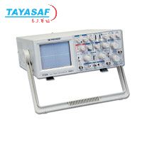
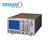
Model 2125A |
|
VERTICAL AMPLIFIERS (CH 1 and CH 2) |
|
Sensitivity |
5 mV/div to 5 V/div, 1 mV/div to 1 V/div at x5 |
|
Attenuator |
10 steps in 1-2-5 sequence. Vernier control provides full adjustment between steps |
|
Accuracy |
+-3%, +-5% at x5 |
|
Input Resistance |
1 MΩ + 2% |
|
Input Capacitance |
25 pF +- 10pF |
|
Frequency Response |
5 mV to 5V/div: DC to 30 MHz (-3 dB)
X5: DC to 10 MHz (-3 dB) |
|
Rise Time |
12 ns (Overshoot <= 5%) |
|
Operating Modes |
CH 1: CH 1, single trace |
|
CH 2 |
CH 2, single trace |
|
ALT |
dual trace, alternating |
|
CHOP |
dual trace, chopped |
|
ADD |
algebraic sum of CH 1 + CH 2 |
|
Polarity Reversal |
CH 2 only |
|
Max. Input Voltage |
400 V (DC to AC peak) |
|
SWEEP SYSTEM |
|
Operating Modes |
Main, mix (both main sweep and delay sweep displayed), or Delay (only delay sweep displayed), X-Y |
|
Main Sweep SpeeD |
0.1 us/div to 2.0 s/div in 1-2-5 sequence, 23 steps Vernier control provides fully adjustable sweep time between steps |
|
Accuracy |
+-3% |
|
Sweep Magnification |
10X, +-5% |
|
Delayed Sweep Speed |
0.1 ms/div to 0.1 s/div in 1-2-5 sequence, 23 steps |
|
Holdoff |
Continuously variable for Main sweep up to 10 times normal |
|
Delay Time Position |
Continuously variable to control percentage of display that is devoted to main and delay sweep |
|
TRIGGERING |
|
Triggering Modes |
AUTO (free run) or NORM, TV-V, TV-H |
|
Trigger Source |
CH 1, CH 2, ALT, EXT, LINE |
|
Maximum External Trigger Voltage |
300 V (DC + AC peak) |
|
Trigger Coupling |
AC 30 Hz to 30 MHz |
|
|
TV H Used for triggering from horizontal syns pulses |
|
|
TV H Used for triggering from vertical syns pulses |
|
TRIGGER SENSITIVITY |
|
Coupling |
Bandwidth |
Int |
Ext |
|
Auto |
100Hz - 40MHz |
1.5 div. |
>=0.1Vp-p |
|
Norm |
100 Hz - 40 MHz |
1.5 div. |
>=0.1Vp-p |
|
TV-V |
DC - 1kHz |
0.5 div |
>= 0.05Vp-p |
|
TV-H |
1 kHz - 100 kHz |
0.5 div |
>= 0.05 Vp-p |
|
|
HORIZONTAL AMPLIFIER (Input through channel 1 input) |
|
X-Y Mode |
Switch selectable using X-Y switch, CH 1: X axis CH 2: Y axis |
|
Sensitivity |
Same as vertical channel 2 |
|
Accuracy |
Y-Axis: +-3%. X-Axis: +-6% |
|
Input Impedance |
same as vertical channel 2 |
|
Frequency Response |
DC to 1 MHz typical (-3 dB), to 6 div horizontal deflection |
|
X-Y Phase Difference |
3 0 or less at 50 kHz |
|
Max. Input Voltage |
Same as vertical channel 2 |
|
CRT |
|
Type |
Rectangular with internal graticule |
|
Display Area |
8 x 10 div (1 div = 1 cm) |
|
Accelerating Voltage |
2 kV |
|
Phosphor |
P31 |
|
Trace Rotation |
Electrical, front panel adjustable |
|
COMPONENT TESTER |
|
Components Tested |
Resistors, Capacitors, Inductors, and Semiconductors |
|
Test Voltage |
6V rms maximum (open) |
|
Test Current |
11 mA maximum (shorted) |
|
Test Frequency |
Line Frequency (60Hz in USA) |
|
Calibrating Voltage |
1 kHz (+-10%) Positive Square Wave, 0.2 V p-p (+-2%) |
|
Other Specifications |
|
Within Specified Accuracy |
50 0 to 95 0 F (10 0 to 35 0 C), <= 85% RH |
|
Full Operation |
32 0 to 104 0 F (0 0 to 40 0 C), <= 85% RH |
|
Storage |
-4 0 to 158 0 F (-20 0 to +70 0 C) |
|
Power Requirements |
Approximately 40 W |
|
All other operating specifications are the same as model 2120A |
|
Dimensions (WxHxD) |
7x14.5x14.25'' (180x370x440 mm) |
|
Weight |
Approximately 17.2 lbs. (7.8 kg) |
|
Three Year Warranty |
|
Accessories |
|
SUPPLIED: Instruction Manual, Two PR-33A x1/x10 Probes or equivalent, AC Power Cord, Spare Fuse
OPTIONAL: PR-32A Demodulator Probe, PR-37A x1/x10/REE Probe, LC-210A Carrying Case |

 泰亚赛福 ―― 世界领先的检测仪器集成供应商

 您当前的位置: